In wave theory, a phased array is a group of antennas in which the relative phases of the respective signals feeding the antennas are varied in such a way that the effective radiation pattern of the array is reinforced in a desired direction and suppressed in undesired directions.[1] Phased array transmission was originally developed in 1905 by Nobel Laureate Karl Ferdinand Braun who demonstrated enhanced transmission of radio waves in one direction.[2] During World War II, Nobel Laureate Luis Alvarez used phased array transmission in a rapidly-steerable radar system for "ground-controlled approach", a system to aid in the landing of airplanes in England. At the same time GEMA in Germany built the PESA Mammut 1.[3] It was later adapted for radio astronomy leading to Nobel Prizes for Physics for Antony Hewish and Martin Ryle after several large phased arrays were developed at the University of Cambridge. The design is also used in radar, and is generalized in interferometric radio antennas. DARPA researchers recently announced a 16 element phased array integrated with all necessary circuits to send at 30–50 GHz on a single silicon chip for military purposes.[4]
An antenna array is a multiple of active antennas coupled to a common source or load to produce a directive radiation pattern. Usually the spatial relationship also contributes to the directivity of the antenna. Use of the term "active antennas" is intended to describe elements whose energy output is modified due to the presence of a source of energy in the element (other than the mere signal energy which passes through the circuit) or an element in which the energy output from a source of energy is controlled by the signal input.
Usage
The relative amplitudes of — and constructive and destructive interference effects among — the signals radiated by the individual antennas determine the effective radiation pattern of the array. A phased array may be used to point a fixed radiation pattern, or to scan rapidly in azimuth or elevation. Simultaneous electrical scanning in both azimuth and elevation was first demonstrated in a phased array antenna at Hughes Aircraft Company, Culver City, CA, in 1957 (see Joseph Spradley, “A Volumetric Electrically Scanned Two-Dimensional Microwave Antenna Array,” IRE National Convention Record, Part I - Antennas and Propagation; Microwaves, New York: The Institute of Radio Engineers, 1958, 204-212). When phased arrays are used in sonar, it is called beamforming.
The phased array is used for instance in optical communication as a wavelength-selective splitter.
For information about active as well as passive phased array radars, see also active electronically scanned array.
Broadcasting
In broadcast engineering, phased arrays are required to be used by many AM broadcast radio stations to enhance signal strength and therefore coverage in the city of license, while minimizing interference to other areas. Due to the differences between daytime and nighttime ionospheric propagation at mediumwave frequencies, it is common for AM broadcast stations to change between day (groundwave) and night (skywave) radiation patterns by switching the phase and power levels supplied to the individual antenna elements (mast radiators) daily at sunrise and sunset. More modest phased array longwire antenna systems may be employed by private radio enthusiasts to receive longwave, mediumwave (AM) and shortwave radio broadcasts from great distances.
On VHF, phased arrays are used extensively for FM broadcasting. These greatly increase the antenna gain, magnifying the emitted RF energy toward the horizon, which in turn greatly increases a station's broadcast range. In these situations, the distance to each element from the transmitter is identical, or is one (or other integer) wavelength apart. Phasing the array such that the lower elements are slightly delayed (by making the distance to them longer) causes a downward beam tilt, which is very useful if the antenna is quite high on a radio tower.
Other phasing adjustments can increase the downward radiation in the far field without tilting the main lobe, creating null fill to compensate for extremely high mountaintop locations, or decrease it in the near field, to prevent excessive exposure to those workers or even nearby homeowners on the ground. The latter effect is also achieved by half-wave spacing – inserting additional elements halfway between existing elements with full-wave spacing. This phasing achieves roughly the same horizontal gain as the full-wave spacing; that is, a five-element full-wave-spaced array equals a nine- or ten-element half-wave-spaced array.
Naval usage
Phased array radar systems are also used by warships of several navies including the Chinese, Japanese, Norwegian, Spanish, Korean and United States' navies in the Aegis combat system. Phased array radars allow a warship to use one radar system for surface detection and tracking (finding ships), air detection and tracking (finding aircraft and missiles) and missile uplink capabilities. Prior to using these systems, each surface-to-air missile in flight required a dedicated fire-control radar, which meant that ships could only engage a small number of simultaneous targets. Phased array systems can be used to control missiles during the mid-course phase of the missile's flight. During the terminal portion of the flight, continuous-wave fire control directors provide the final guidance to the target. Because the radar beam is electronically steered, phased array systems can direct radar beams fast enough to maintain a fire control quality track on many targets simultaneously while also controlling several in-flight missiles. The AN/SPY-1 phased array radar, part of the Aegis combat system deployed on modern U.S. cruisers and destroyers, "is able to perform search, track and missile guidance functions simultaneously with a capability of over 100 targets."[5] Likewise, the Thales Herakles phased array multi-function radar onboard the Formidable class frigates of the Republic of Singapore Navy has a track capacity of 200 targets and is able to achieve automatic target detection, confirmation and track initiation in a single scan, while simultaneously providing mid-course guidance updates to the MBDA Aster missiles launched from the ship.[6] The German Navy and the Dutch Navy have developed the Active Phased Array Radar System (APAR).
Mathematical perspective and formulas
A phased array is an example of N-slit diffraction. It may also be viewed as the coherent addition of N line sources. Since each individual antenna acts as a slit, emitting radio waves, their diffraction pattern can be calculated by adding the phase shift φ to the fringing term.
We will begin from the N-slit diffraction pattern derived on the diffraction page.
![\psi ={{\psi }_0}\left[\frac{\sin \left(\frac{{\pi a}}{\lambda }\sin\theta \right)}{\frac{{\pi a}}{\lambda }\sin\theta}\right]\left[\frac{\sin \left(\frac{N}{2}{kd}\sin\theta\right)}{\sin \left(\frac{{kd}}{2}\sin\theta \right)}\right]](http://upload.wikimedia.org/math/5/c/e/5ced075993b8410cdf357c301b644b88.png)
Now, adding a φ term to the  fringe effect in the second term yields:
![\psi ={{\psi }_0}\left[\frac{\sin \left(\frac{{\pi a}}{\lambda }\sin \theta\right)}{\frac{{\pi a}}{\lambda }\sin\theta}\right]\left[\frac{\sin \left(\frac{N}{2}\big(\frac{{2\pi d}}{\lambda }\sin\theta + \phi \big)\right)}{\sin \left(\frac{{\pi d}}{\lambda }\sin\theta +\phi \right)}\right]](http://upload.wikimedia.org/math/2/d/3/2d37c7be4f9b566214bc13a290439570.png)
Taking the square of the wave function gives us the intensity of the wave.
![I = I_0{{\left[\frac{\sin \left(\frac{\pi a}{\lambda }\sin\theta\right)}{\frac{{\pi a}}{\lambda } \sin [\theta ]}\right]}^2}{{\left[\frac{\sin \left(\frac{N}{2}(\frac{2\pi d}{\lambda} \sin\theta+\phi )\right)}{\sin \left(\frac{{\pi d}}{\lambda } \sin\theta+\phi \right)}\right]}^2}](http://upload.wikimedia.org/math/1/3/3/1332e02f034201f7bc0d3de036e3c27c.png)
![I =I_0{{\left[\frac{\sin \left(\frac{{\pi a}}{\lambda } \sin\theta\right)}{\frac{{\pi a}}{\lambda } \sin\theta}\right]}^2}{{\left[\frac{\sin \left(\frac{\pi }{\lambda } N d \sin\theta+\frac{N}{2} \phi \right)}{\sin \left(\frac{{\pi d}}{\lambda } \sin\theta+\phi \right)}\right]}^2}](http://upload.wikimedia.org/math/3/5/3/353b4dcb6b13c5cc3095a185910ff5d6.png)
Now space the emitters a distance  apart. This distance is chosen for simplicity of calculation but can be adjusted as any scalar fraction of the wavelength.
![I =I_0{{\left[\frac{\sin \left(\frac{\pi }{\lambda } a \theta \right)}{\frac{\pi }{\lambda } a \theta }\right]}^2}{{\left[\frac{\sin \left(\frac{\pi }{4} N \sin\theta+\frac{N}{2} \phi \right)}{\sin \left(\frac{\pi }{4} \sin\theta+ \phi \right)}\right]}^2}](http://upload.wikimedia.org/math/1/d/a/1da053851c4c364b2dc3a87770813193.png)
Sin achieves its maximum at  so we set the numerator of the second term = 1.


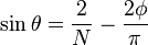
Thus as N gets large, the term will be dominated by the  term. As sin can oscillate between −1 and 1, we can see that setting
  will send the maximum energy on an angle given by
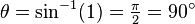
Additionally, we can see that if we wish to adjust the angle at which the maximum energy is emitted, we need only to adjust the phase shift φ between successive antennas. Indeed the phase shift corresponds to the negative angle of maximum signal.
A similar calculation will show that the denominator is minimized by the same factor.
Different types of phased arrays
There are two main different types of phased arrays, also called beamformers. There are time domain beamformers and frequency domain beamformers.
A time domain beamformer works, as the name says, by doing time-based operations. The basic operation is called "delay and sum". It delays the incoming signal from each array element by a certain amount of time, and then adds them together. Sometimes a multiplication with a window across the array is done to increase the mainlobe/sidelobe ratio, and to insert zeroes in the characteristic.
There are two different types of frequency domain beamformers. The first type separates the different frequency components that are present in the received signal into different frequency bins (using either an FFT or a filterbank). When different delay and sum beamformers are applied to each frequency bin, it is possible to point the main lobe to different directions for different frequencies. This can be an advantage for communication links.
The other type of frequency domain beamformers makes use of so called Spatial Frequency. This means that an FFT is taken across the different array elements, not in time. The output of the N point FFT are N channels, which are evenly divided in space. This approach makes a simple implementation of several beamformers at the same time possible, but this approach is not flexible, because the different directions are fixed.
Saya rasa disini telah terjawab soalan untuk 9w2VEB....
73
de GRAM
ASSALAMUALAIKUM